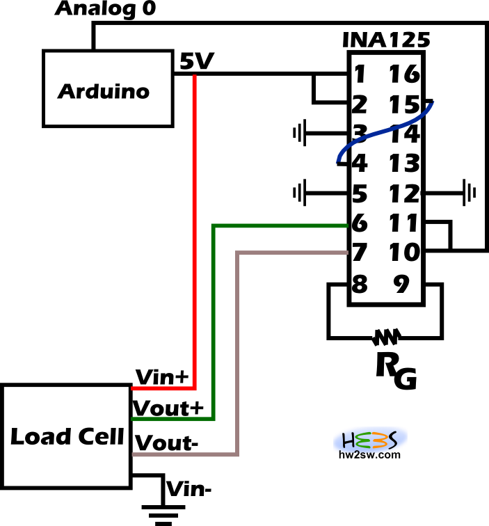
Ina125 Load Cell Circuit

Ina125 Single Supply Small Weight Problems Electrical Engineering Stack Exchange

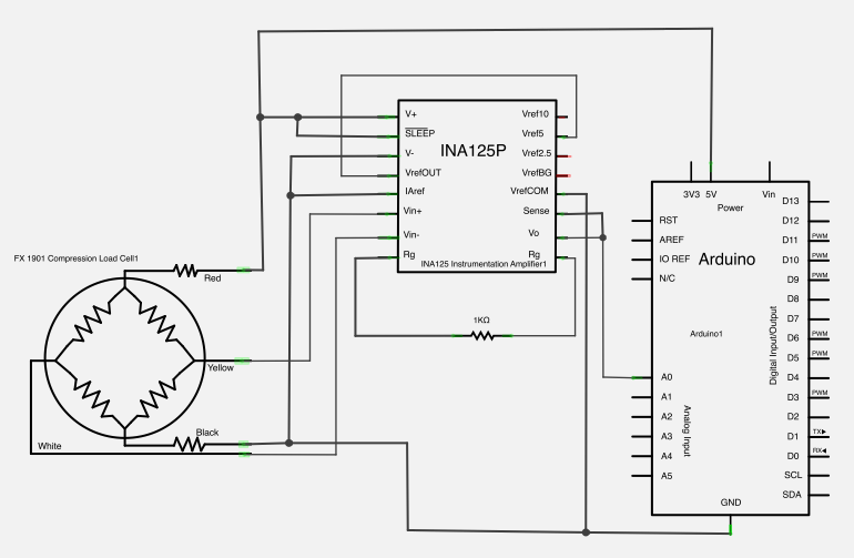
Building A Low Cost Strain Gage Load Cell Amplifier The Mechtech Place

Load Cell With Ina125p

Arduino Leonardo 3 Wire Load Cells Ina125p Analog Signal Bounce Noise Electrical Engineering Stack Exchange
Problem With Ina125
Load Cell Ina125p Analogreference Signal Stability

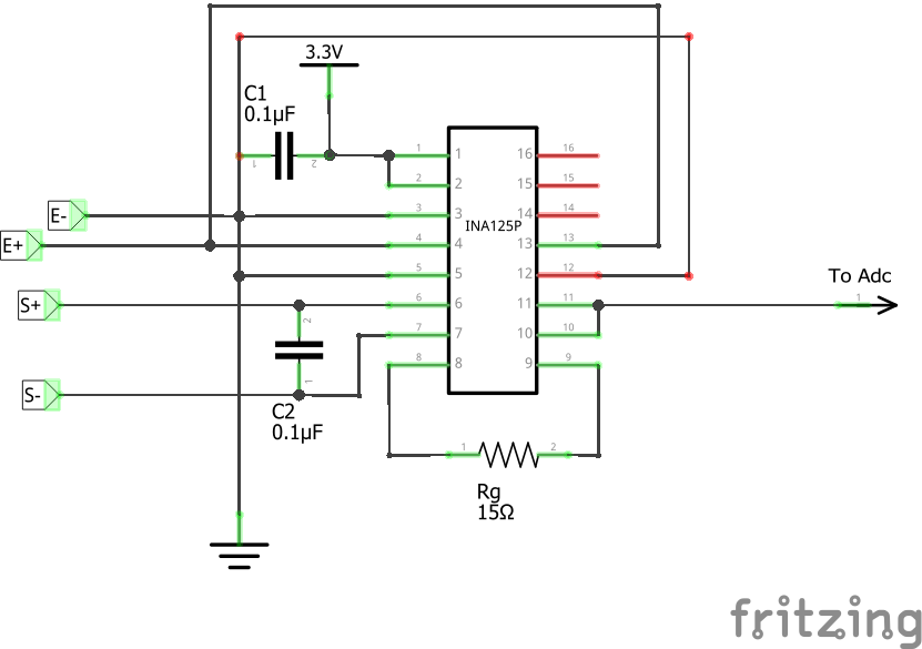
The circuit from the data sheet can be seen below.
Ina125 load cell circuit.
Load Cell Sensor With Ina125 Amplifiers Forum Amplifiers Ti E2e Support Forums
Air Command Water Rockets Flight Log Day 67 Test Stand Work
Resolved Ina125 Bad Data Captured From Adc Amplifiers Forum Amplifiers Ti E2e Support Forums

Figure A1 The Circuit Arrangement Of The Instrumentation Amplifier Download Scientific Diagram
Source : pinterest.com
